Why Spooling and Rotation Failures Usually Start Long Before Anyone Notices
A wire rope can be installed cleanly, run smoothly for weeks, and still fail in a way that looks like bad material or improper use. When spooling starts drifting to one side, the hook block begins to rotate, or birdnesting shows up near the flange, the problem is usually blamed on the rope itself. In reality, those symptoms are often the delayed result of geometry that was never controlled, a rope forced to enter the system in a way it cannot tolerate.
Fleet angle is the difference between a rope that runs clean and a rope that starts piling, twisting, and birdnesting months later. When setup geometry forces the rope to enter the drum or sheaves at the wrong angle, the rope rolls into grooves, picks up unwanted torsion, and shows its damage first where the angle peaks, most often near the flange. Until fleet angle is treated as a system behavior tied to rope construction and groove condition, replacing the rope will only repeat the same failure.
Why Fleet Angle Failures Usually Start During Setup
Most fleet angle problems are created before the rope ever carries a meaningful load. The installation phase is where geometry is established, and it is also where it is easiest to compromise without realizing it.
One of the most common contributors is payoff positioning. When a new spool of wire rope is placed too close to the first point of contact on the drum, the lateral approach increases quickly. This often happens when space is limited, when the focus is on keeping the rope off the floor, or when payoff placement is treated as a temporary convenience rather than a controlling variable.
The setup may look acceptable at first. Initial wraps seat cleanly, and early cycles run without incident. What is easy to miss in that moment is that the rope is already being forced into the drum at an angle it will carry for the rest of its service life. Fleet angle does not correct itself once the system is running. Every wrap reinforces the same behavior, and any stress introduced early becomes part of how the rope responds under load later.
This is why fleet angle should be treated as an installation condition rather than a maintenance issue. By the time symptoms appear, the setup decisions that caused them are usually long forgotten.
Fleet Angle, Defined Only as Much as You Need
Fleet angle describes the lateral approach of a rope as it travels toward a drum or sheave. In practical terms, it captures how straight or offset the rope is when it enters a groove. A small amount of fleet angle is necessary to allow the rope to traverse across the drum face. Without it, the rope stacks in place and fails to cross properly. Too much fleet angle, however, forces the rope to ride up the groove wall and roll into position rather than seating directly. That rolling motion is where many downstream problems begin.
Fleet angle is not uniform across the drum. It increases as the rope approaches the flange and reaches its maximum on the last wrap. This uneven distribution explains why damage patterns tend to cluster near the flange rather than appearing evenly across the drum. Understanding fleet angle at this level is sufficient for diagnosing behavior. The goal is not precise calculation for its own sake, but recognizing when geometry is forcing the rope to behave unnaturally.
Practical Fleet Angle Targets by Rope Type
Fleet angle limits exist because different wire rope constructions respond differently to lateral entry. Treating all ropes as interchangeable in this regard is one of the fastest ways to create unstable spooling and rotation problems.
| Rope Construction | Practical Installation Target | Dominant Risk When Exceeded |
| Rotation-Resistant | ≤ 2° | Internal torque, block rotation, birdnesting |
| Standard / Non-Rotation-Resistant | ≤ 4° | Uneven spooling, accelerated wear |
Rotation-resistant ropes are particularly sensitive because their internal structure is designed to counteract torque under load. When these ropes are forced to roll into grooves due to excessive fleet angle, internal torsion is introduced that the construction is specifically meant to avoid. The result is rotation under load, unstable spooling, and, in severe cases, structural distortion.
Standard and non-rotation-resistant ropes tolerate greater lateral approach, but that tolerance has limits. As fleet angle increases, contact with groove walls becomes more aggressive, and wear patterns accelerate. At that point, spooling behavior becomes unpredictable even if load, lubrication, and handling are otherwise appropriate.
These values should be understood as geometry control targets, not guarantees. They assume that grooves are correctly sized and that the rope is free to respond naturally to load.
What Excessive Fleet Angle Does Inside the Groove
When fleet angle exceeds what the system can tolerate, the rope’s interaction with the groove changes in a fundamental way. Instead of settling directly into the lowest point of the groove, the rope contacts the groove wall higher up and rolls down into position. That rolling motion occurs repeatedly, wrap after wrap, cycle after cycle. Each time it happens, torsional energy is introduced into the rope.
Over time, that torsion shows up as behavior. The rope begins to favor one side of the drum even when the traverse mechanism is functioning correctly. Hook blocks rotate under load, sometimes intermittently and sometimes continuously. As the condition persists, wraps lose tension discipline and cross improperly, leading to birdnesting.
These symptoms are not independent failures. They are mechanically linked expressions of lateral entry, forcing the rope to behave in ways it was not designed to handle.
The Three Early Signs You’re Exceeding Fleet Angle
Fleet angle rarely announces itself directly. Instead, it shows up through behavior that is easy to misinterpret if viewed in isolation.
· Rope begins piling consistently on one side of the drum rather than traversing evenly across the face.
· Hook block rotation develops under load, even when rotation had not previously been an issue.
· Birdnesting appears as wraps lose stability and cross improperly, often near the flange.
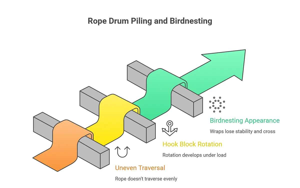
What connects these symptoms is how the rope enters and seats in the groove. Excessive lateral approach forces the rope to roll into position, which introduces twist. Treating these signs as separate problems often leads to piecemeal fixes that fail to address the underlying geometry.
Why Problems Show Up Near the Flange First
Fleet angle increases as the rope approaches the flange, reaching its highest value on the last wrap. This area experiences the greatest lateral deflection and the strongest tendency for the rope to ride high in the groove before seating.
When fleet angle is excessive, the cumulative effects of rolling and side contact concentrate here first. Protruded cores, localized birdnesting, and severe spooling irregularities near the flange are rarely coincidental. They are physical records of sustained lateral entry.
An inspection that ignores the last wraps often misses the clearest evidence of fleet angle problems. When damage clusters near the flange, geometry should be evaluated before load, lubrication, or material quality are questioned.
When Fleet Angle Is “In Range” but the Rope Still Suffers
Fleet angle alone does not determine rope performance. Groove condition plays an equally important role and can override otherwise acceptable geometry.
Oversized or worn grooves fail to support the rope along its sides, allowing it to flatten and increasing internal stress. Undersized or peaked grooves pinch the rope along narrow contact lines, creating localized pressure that damages wires and promotes distortion. In both cases, the rope may be entering the system at an acceptable fleet angle while still being subjected to destructive forces within the groove.
This is why fleet angle should never be evaluated in isolation. Groove geometry determines how lateral forces are transmitted into the rope. If grooves are out of tolerance, correcting fleet angle alone will not prevent repeat failures.
The “Helpful” Install Fix That Creates Two Fleet Angles
A common response to installation challenges is adding a sheave block between the payoff spool and the equipment. This is often done to keep the rope off the floor or to reduce the apparent fleet angle at the drum.
What is frequently overlooked is that this introduces a second fleet angle. One angle exists between the payoff spool and the added sheave, and another between the sheave and the drum. Even if the crane or winch is well aligned with the sheave, the spool may not be. In that case, excessive lateral entry occurs upstream of the equipment, before the rope ever reaches it.
Adding components increases the number of variables that must be controlled. Unless both fleet angles are measured and managed, the same geometry problem is recreated in a less visible form, allowing torsion to accumulate unnoticed.
What to Capture before You Order another Rope
When spooling or rotation problems occur, repeat failures are most often caused by replacing the rope without documenting the conditions that damaged the previous one. The goal is not more information, but the right information.
Start with rope construction, because it determines sensitivity to induced torque. Note whether the rope is rotation-resistant or standard, along with diameter and any known restraints on rotation. Document spooling behavior near the flange, because that is where excessive fleet angle reveals itself most clearly. Photographs of the last wraps often separate geometry problems from generalized wear.
Record the full rope path, including every sheave the rope passes over and any sheave blocks added during installation. Added components frequently explain why problems appear even when the system seems aligned. Evaluate groove condition separately, because worn or out-of-tolerance grooves can damage the rope regardless of the fleet angle. Finally, note how the rope was introduced to the system, including payoff distance and alignment relative to the drum lead.
Collecting this information shifts the conversation from replacement to diagnosis and reduces the likelihood of installing a second rope into the same unresolved geometry problem.
Working Through the Problem Together
Fleet angle failures are rarely sudden. They develop quietly, beginning with the setup geometry and progressing over time into spooling instability, rotation, and structural damage. When fleet angle is treated as a system behavior rather than a tolerance to stay within, these patterns become easier to recognize and correct.
At Bilco Group, this is how we work with our customers. The goal is not simply to supply another rope, but to understand how the rope is being asked to behave in the system it lives in. When geometry, rope construction, and groove condition are aligned, rope life improves, and repeat failures disappear. If you are seeing piling, rotation, or birdnesting and want to work through the underlying cause, we’re ready to look at the system with you and help get it right.